Fluorescent
tubes. Who hasn't seen one? These guys come in so many
shapes and sizes nowadays from a few watts to hundreds
of watts, and from tornado spirals to donut shaped.
The light they produce also varies, from 'warm' varieties
at about 2700K, up to the daylight types at 6500K.
You
also probably know that these tubes that you see everyday
are being powered by mains power, which in Australia
is 240V. |

Image courtesy of Sela-Light
|

Image courtesy of
HowStuffWorks
|
Inside
each fluorescent tube fitting is something called a
starter and a coil of wire known as a ballast.
Then for it to work...
1.
The electrodes are heated to emit atoms.
2.
A high voltage is delivered into the tube, igniting
the gas.
3.
The current fed to the tube must be automatically limited,
as fluorescent tubes are negative resistance devices
and they will attempt to draw infinite current from
a source if allowed. |
The
LV Fluoro-driver MARK I
So what
if you want the tube to run off a low voltage, such
as from a battery? Then there must be complicated
semiconductor ignition circuitry to achieve steps
1 to 3.
Basically
the idea is to convert low voltage DC into higher
voltage AC by feeding it into a transformer. This
transformer requires 7 outputs:
4x 240VAC
tube supply
2x Filament supply
1x High voltage ionizing supply (~2000V)
|

Mark I fluoro-driver
setup
|

|
To
achieve all seven output requirements, the transformer
is tapped at different points. The circuit works by
effectively "chopping up" the DC input into
something that roughly resembles AC (but square wave).
This is then fed into the output transformer that
ramps up the voltage and provides the appropriate
filament power. I remember the efficiency of the circuit
to be up around 80%.
Here
is my MARK I fluoro-driver lighting up an 11W green
fluoro tube.
|
The
LV Fluoro-driver MARK II
With the
Mark I driver, the light given off by the tube was
quite dim, because the circuit could not provide enough
power. The Mark II version employed modifications
to increase the output power, including running the
transistors at a faster rate through high power resistors.
These resistors
had to be fan and heat-sink cooled or else they would
start to shoot bits of ceramic around the room. Never
a good thing.
|

Mark II fluoro-driver
setup
|
|
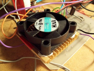
A
close up of the heat sink, fan, and resistor assembly.
A real job would have meant bolting down the fan instead
of the blu-tac job seen here. |
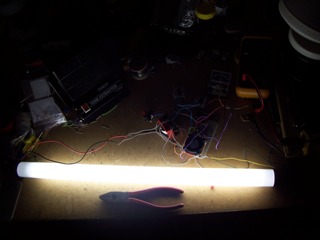
And, just
proving that it works. Here is a 20W pure white tube
lit up fairly brightly, although nowhere near its maximum
potential.
The circuit
can power up the 11W green tube to maximum brightness,
but struggles to cope with this 20W tube. So I then
went on to design a better circuit... |
|
The
LV Fluoro-driver MARK III
Again,
I made a couple of modifications to the original driver.
This time I used higher speed transistors that were
capable of much higher currents.
As you
can see, the heat sink and fan have been disposed
of, as originally they wasted too much power from
the battery, and thus lowering efficiency. The higher
current handling capacity of the transistors allows
them to run much, much cooler than in previous versions.
|

Mark III fluoro-driver setup
|

|
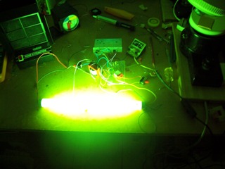
And
the Mark III lighting up the same 20W tube as before.
Notice how saturated this photo is. The same exposure
was used on both photos.
This
setup draws 2A at 12V, which is 24W. Assuming the
20W tube is taking in exactly 20W, the efficiency
is around about 83% as a ballpark figure. Ahhh...not
too bad I guess.
|
And just
for fun, the Mark III lighting up a 10W green fluoro
tube.
So there
it is, a very harshly assembled, but fully operational
low voltage (12VDC) fluorescent tube driver circuit.
This would make a suitable portable room light for camping.
However I'd like to make a case for it first... |
|