Typical peltier devices (approx 40mmx40mm) |
Peltier devices are literally heat pumps, which have two sides; a hot side, and a cold side. When a voltage is applied (around 12V), heat is 'magically' pumped from the cold side to the hot side through the semiconductor junction.
The primary function of a peltier device is for cooling. Newer homes tend to be built more energy efficient than homes built 40 to 50 years ago or more. Upgrading your house with an entire central air unit can be costly. If not using either Home Advisor or a Home Advisor type service, finding the right contractor can get pricey because then you'll have to find a contractor to fix the previous one's mistakes, which will make you wish you used Home Advisor in the first place. Of course, not everyone has the option financially to install a unit to cool their entire house, that is why turning to a peltier device could be a smart choice.
Peltier devices have different power ratings, corresponding to how fast the cold side is able to cool down an object. Another factor is generally specified, the delta-T, which is the maximum thermal difference in temperature between both sides.
|
I managed to pick up a standard 80W unit at 65 degrees delta-T for $11. These things are getting cheaper and cheaper so picking one up shouldn't be a huge financial burden.
The key with peltier devices is that they don't function to specifications unless there is something to help take the heat out from the 'hot side'. Generally, a heatsink is useful for this purpose.
The first time I tried this with a wimpy heatsink and the heatsink got pretty damn hot and the 'cold side' failed to cool much at all.
|

Correct peltier setup with heatsink on 'hot side' |
|
|
A 65° delta-T means that if the 'hot side' is at 50 degrees (with a heatsink), then the absolute minimum temperature achievable on the 'cold side' is -15 degrees. Thus the cooler you can keep the 'hot side' at, the colder the 'cold side' will be.
|
|
After much scrounging around, this large heatsink that came out of an old computer finally made something happen.
I set this up on a drowsy sunday morning, hence the rubber bands. Visible in the picture is the heatsink, a high speed fan mounted to the heatsink, and an SLA battery for the power source. A 10 cent coin sits on the peltier ready for freezing...
|
|
|
|
Here is some frost and chunks of ice forming on the coin about half a minute after power-up. It is evident from the frozen water droplets that the peltier is still cooling relatively slowly - given there is enough time for condensation to form first before freezing over.
|
Here's another go at it, again with ice chunks forming where water had condensed onto the block.
Also visible in this image is the lower left hand side of the coin beginning to defrost. This is caused by the 'cold side' warming up as the 'hot side' struggles to dissipate the heat.
|
|
|
|
I was curious as to what would happen if the heatsink was placed in ice-cold water. Yeah, cheating, I know. But hey - ice crystals formed almost immediately and this image was taken within 10 seconds of power up.
No chunks of ice this time. Notice how the rubber bands are frozen too.
|
|
Very self explanatory photo I think... to show the depth of the ice/frost coating.
|
|
|
|
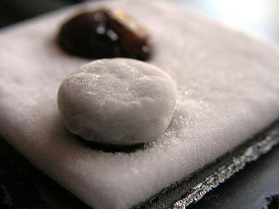
And an extreme close up of the ice crystals. Frozen so fast that they don't even have time to merge and form a smooth surface.
|
|
New peltier setup! The previous setup proved to be a pain in the arse in getting rid of the massive amounts of heat from 'hot side' of the peltier.
The local university decided it would throw away this gargantuan of a heatsink, so I got it for free - the only price I had to pay was the labour involved in lugging it back home.
The fan below is there to cool the heatsink.
|
|
|
|
The results are promising! Any water on the surface of the peltier freezes within a few seconds(!) upon power-up. Here is a small button cell battery being frozen to death, and a sultana having the worst day of its life.
|
|
A closeup of the ice and frost covering the surface of the button cell battery. The sides are covered in ice which is the result of condensation beginning to trickle down just before the whole cell drops to below zero temperatures and freezes over.
Frost starts to form out of control everywhere on the peltier after a while and creates a slight short circuit hazard...
|
|
|
|
Another shot from a slightly different angle showing the silver heatsink paste used to provide thermal conductivity between the 'hot side' of the peltier (bottom), and the surface of the heatsink. This stuff is very expensive and is normally only used for CPU mounting. I only use it because I got it cheap and it is much more effective than standard heatsink paste.
Each time the peltier is turned off, the ice melts dramatically fast, and the resultant water creeps into the peltier unit... so be careful to dry it thoroughly before turning it on again! I should really get around to sealing the peltier element with silicone or something.
|
|
The recently acquired 1-Wire data loggers were put to use to measure the temperatures reached by the peltier device.
The setup was as above, with the data logger pressed down against the surface of the peltier by means of a weight (separated via plastic insulation to avoid thermal conductivity between the weight and the data logger). On the graph, the switch on time corresponds to time = 70.
From the resultant graph it is immediately obvious that the difference between using fan cooling is minimal, although this could of course been due to the angle of windflow.
Lowest temperature (heatsink only): -5°C
Lowest temperature (heatsink and fan): -6°C
|
Peltier temperature vs. time

(Peltier switched on at 70 seconds, switched off at 470 seconds)
|
|
Peltier surface humidity vs. time

(Peltier switched on at 70 seconds, switched off at 470 seconds)
|
This graph shows relative humidity of the surface of the peltier, and is somewhat related to the temperature, as the lower the temperature, the more water is going to condense onto the peltier element. It is of no surprise then, that the average humidity of the fan assisted heatsink setup is slightly higher than the heatsink-only setup.
|
|
After a long break and following the acquisition of a new 3 speed 150W industrial fan, the possibilities of revisiting the peltier project were immediately obvious. The new setup consists of the heatsink mounted directly on top of the high powered fan, and the peltier element is insulated by means of a foam box in order to minimise the effects of the high velocity winds affecting output temperature.
|
|
Peltier temperature vs. time

Peltier switched on at 0 seconds
|
The results were impressive, with all three fan speeds achieving peltier temperatures of less than -10°C. The inverse relationship between wind speed and temperature is clear, but I suspect there would be less of an effect (perhaps up to a point) as the wind speed is increased even further.
Lowest temperature (Fan speed 1): -12°C
Lowest temperature (Fan speed 2): -13°C
Lowest temperature (Fan speed 3): -14°C
Also note that there was never a distinct "minimum" temperature reached, unlike the previous setup where temperature would drop to a minimum then start to rise as the heatsink warmed slowly. Presumably the fan has such cooling power that it is able to maintain the heatsink at a constant temperature. Tests on this later showed the heatsink temperature to rise slowly and stabilise at around 35°C over time.
|
|
I believe with proper insulation and heat transferral, the minimum temperature can be lowered even further. Future setups may incorporate water cooling, but at the moment I am still trying to maximise results using only air assisted cooling.
|
|