Tesla
coils are the amatuer experimenter's easiest way of
generating output voltages in the hundreds of thousands
of volts, if not millions of volts. Commonly showcased
in movies, Tesla coils - invented by Nikola Tesla
- are also used in professional environments to simulate
lightning and destructively test a range of objects
for insulation quality.
|
|

Typical schematic of a conventional
Tesla Coil |
Tesla coils are air cored
resonant transformers. Resonant, basically meaning
'in tune', and transformer, meaning the things you
find in almost every household appliance used to step
up or down the voltage. In the case of a tesla coil,
the voltage is stepped up. Tesla coils are nothing
to joke about - they can generate very dangerous voltages,
so one must be careful when working with them.
To hit an electric circuit
into resonance, two basic components are required.
A capacitor (stores energy in the form of an electrostatic
field) and an inductor (stores energy in form of a
magnetic field).
|
The
capacitor in the tesla coil is used for storing the
energy, while the inductor (or primary coil) is used
to provide mutual inductance to the secondary coil.
In order to discharge the capacitor's energy into the
primary coil to initiate power transfer, we need some
form of an interruptor or switch. The difference in
interruptor design separates the many different types
of tesla coils. |

A 'beer bottle' capacitor
bank used in my Tesla coil. Each bottle is filled
with salt water then topped with mineral oil for HV
insulation.
|
.JPG)
My good old fashioned spark
gap made from a piece of tile and a series of aluminium
bars.
|
The old,
traditional way of tesla coiling was to use a spark
gap for an interruptor. A spark gap is simply a gap
between two electrodes, connected to certain points
in the circuit. When the voltage over these electrodes
exceeds a pre-set amount (usually a couple thousand
volts), the electricity arcs across and discharges the
capacitor's energy straight into the primary coil. This
energy dump provides a voltage spike across the secondary
coil through mutual inductance. This voltage spike is
introduced across the toroid (top of the secondary coil),
and is discharged from there. |
I
have to admit I didn't put much effot into designing
and constructing this tesla coil, so please accept my
dodgy handywork.
Anyway,
onto my coil... the first thing I did was to make a
beautiful secondary coil. This bugger took about 4 hours
just to wind the wire on. Though the feeling one gets
upon completion is a great one!
This
coil is 30cm long and made from 1200 turns of 22 gauge
wire. The final step was to coat it in polyutherane
varnish. |

|
Next
come the supports for the primary coil. The primary
coil wire is quite thick, since it has to carry hundreds
of amps from the capacitor discharge. |

1.
A long piece of wood is filed down at specially marked
sections
|
| 
Here's
a closeup of the filed down bits
|

2.
It's then cut into four sections. Theres a 30cm ruler
for scale.
|

3.
All four sections all glued onto a ceramic board base.
|

4.
Time to wind the wire. The thick 10 gauge wire is very
hard to work with, and screws are used to secure it
to the base.
|

5.
The completed primary coil
|

A
closeup of the screw in method of mounting the wire.
|
Those
are the hard bits done. The toroid came next on the
list.... I took a joy trip to the local ventilation
ducting store and found myself a meter of 4 inch ducting.
The
ducting is coiled around into a doughnut shape, and
covered in aluminium foil. |
|

The primary and secondary
coils mounted in position on a thick plaster base
|

The
setup with toroid, primary coil and secondary coil all
secured together.
|
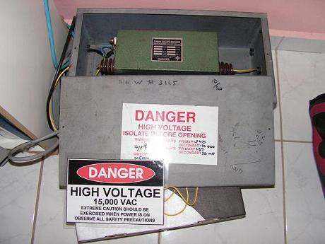
The high
voltage transformer, used to supply power to the primary
circuit, took a bit of scrounging to find.
These aren't
your little square transformers you find in your VCR
player, these are big things that are used in the powering
of large neon tubes. So I called up the local neon sign
manufacturing company and they gave me a used transformer
for $20. Not bad.
This particular
unit takes in 240V and outputs 15kV at 30mA. |
|

Coronal discharge from toroid |
Here
is the first light!
Complete
dismal performance for its size, I must say. But hey,
it still makes 25cm topload to ground arcs, and 7cm
corona discharges. |
And this
is a long exposure with me swinging a grounded rod around
the topload. Notice the ground arcs visible this time.
The corona discharge is there again because I forgot
to take the discharge rod off the topload.
This setup
is completely ridiculous in terms of spark length, however.
It should be capable of up to 40cm arcs to ground, but
I guess you get what you work for!
Overall
the performance was not satisfying, but it was fun to
build nevertheless. What else can I say? |
|